


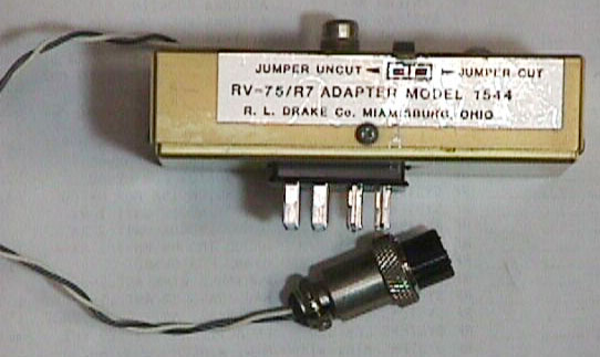


The R.L. Drake 1544 adapter pictured to the left is a small box that allows the Drake
R7 or R7A to work with the Drake RV75 digital VFO, giving the R7 rock solid
frequency stability, variable rate tuning and two programmable fixed frequencies.
The 1544 into the the accessory socket of the R7 and the RV75's cable plugs into the
1544. Transceive capability between the TR7 and the R7 is retained by plugging the
transceive cable from the TR7 into the 1544, rather than the accessory socket of the
R7. The short two wire cable coming out of the 1544 plugs intothe R7’s 13.8VDC
accessory socket to power the RV75.
Unfortunately, the Drake 1544 adapter is a rare item and no longer in production. To fill the void, we looked into what it would take to replicate a 1544.
Drake made the 1544 a bit more complicated than needed by designing the 1544 to work when fixed frequency crystals were installed in the AUX-7 board of the R7 (see the original schematic, figure 2). Our designed skipped this complexity, since the crystal controlled fix frequency capability of the R7 is rarely used and is somewhat unnecessary when used with the R75 (see the modified schematic, figure 3). As a bonus, our modification avoids the need to internally modify the R7, that might have been required with the original Drake 1544. In short, our version of the Drake 1544 adapter will work on both the R7 and the R7A receivers. However, it will only work with receivers that have not been modified per Drake’s 1544 instructions and will not work properly if accessory crystals are installed in the R7/R7A AUX-7 board.
Here is the complete parts list for the adapter:
1 Bud diecast utility box 3.68”x1.50”x1.08” #1590A
1 Cinch Jones 8 pin socket (female) connector with angle bracket
1 Cinch Jones 12 pin socket (female) connector with angle bracket (see text)
1 Cinch Jones 12 pin plug (male) connector with angle bracket (see text)
1 RCA phono jack, chassis mount with ground lug
1 Two connector female Amphenol connector
1 Chassis grommet
1 10K ½ watt resistor
Several pieces of 22 gage single strand bare wire
Several pieces of 22 gage multistranded hookup wire
First, we prepared the utility box by cutting the holes for the three Cinch connectors, the RCA phono jack and the grommet for the power cable. The holes for the Cinch connectors were cut to be just big enough to accommodate the front of the connectors. The hole for the twelve pin plug was cut in the bottom of the utility box and slightly offset from center to clear both the R7’s voltage select slide switch on the left and the speaker jack on the right (see figures 4 and 7). The hole for the twelve-pin socket was cut in the lid exactly opposite the hole in the box’s bottom.
The Cinch sockets and plug are designed for chassis mounting (that is, they have what Cinch calls angle brackets) and may be hard to find. However, the twelve-pin socket and plug do not necessarily need the angle brackets, as explained later on. The eight-pin socket will need the angle bracket, though.
The angle brackets (mounting tabs) of the Cinch Jones 12 pin plug and socket were too big to allow mounting in the box and needed to be shortened at about the middle of the mounting holes so that they just fit the inside of the box (since the plug and socket would “float” in the box, the bracket mounting holes weren’t needed).
As shown in the schematic, pins 7, 8 and 10 of the socket are unused so were cut off at the solder end in order to prevent these pins from shorting to the corresponding pins of the plug. Then the Cinch Jones 12 pin plug and socket were wired together back to back, by soldering corresponding plug and socket pins 1-6, 9, 11 and 12 together using small pieces of 22 ga single strand hookup wire. As luck would have it, the resulting assembly height was the same depth as the Bud box. This allowed the assembly to “float” in the adapter, held in place by the angle brackets and the cutouts in the box that were just big enough for the front of the connectors.
Lengths of 22 gage multistrand hookup wire were used to connect pins 3, 7 and 10 of the Cinch Jones 12 pin plug to the 8 pin socket. The completed assembly is shown in figure 5.
Using the R7 accessory jack to correctly orient the polarized plug, we laid the assembly into the box lid. After jumpering pins 5 and 7 of the Cinch Jones 8 pin socket connector (as shown in figure 3), we mounted the 8 pin socket connector, the RCA phone jack and the chassis grommet to the lid of the box. Using the schematic (figure 3) as a guide, we finished wiring the three loose wires and the other end of the 10K resistor to the Cinch Jones 8 pin socket connector and RCA jack (figure 6).
Using a 10” piece of twisted pair 22 gage multistrand hookup, we wired the Amphenol connector to pins 1 and 3 of the Cinch Jones 8 pin socket connector, making sure that we observed the correct polarity (Pin 3 of the Cinch Jones to the + lead and pin 1 to the – lead, using the polarity marked on the back of the R7 next to the mating Amphenol socket.)
We completed the adapter by fastening the box lid to the box using the supplied machine screws, and then plugged the adapter into the accessory plug of the R7. We found that a more secure fit to the R7 was achieved by removing the interfering screw that helps secure the R7’s input voltage selector plate.
Cabling the new adapter simply meant plugging the RV75’s two cables into the adapter and plugging the adapter’s Amphenol plug into the R7’s Amphenol 13.8V socket (this is the source that powers the RV75). See figure 7.
In order for the RV75 to control the R7’s frequency it is necessary to push in the R7’s “fixed” button. To revert back to the R7’s internal VFO, turn the RV75 to off and leave the “fixed” button in the out (off) position.
Unfortunately, the Drake 1544 adapter is a rare item and no longer in production. To fill the void, we looked into what it would take to replicate a 1544.
Drake made the 1544 a bit more complicated than needed by designing the 1544 to work when fixed frequency crystals were installed in the AUX-7 board of the R7 (see the original schematic, figure 2). Our designed skipped this complexity, since the crystal controlled fix frequency capability of the R7 is rarely used and is somewhat unnecessary when used with the R75 (see the modified schematic, figure 3). As a bonus, our modification avoids the need to internally modify the R7, that might have been required with the original Drake 1544. In short, our version of the Drake 1544 adapter will work on both the R7 and the R7A receivers. However, it will only work with receivers that have not been modified per Drake’s 1544 instructions and will not work properly if accessory crystals are installed in the R7/R7A AUX-7 board.
Here is the complete parts list for the adapter:
1 Bud diecast utility box 3.68”x1.50”x1.08” #1590A
1 Cinch Jones 8 pin socket (female) connector with angle bracket
1 Cinch Jones 12 pin socket (female) connector with angle bracket (see text)
1 Cinch Jones 12 pin plug (male) connector with angle bracket (see text)
1 RCA phono jack, chassis mount with ground lug
1 Two connector female Amphenol connector
1 Chassis grommet
1 10K ½ watt resistor
Several pieces of 22 gage single strand bare wire
Several pieces of 22 gage multistranded hookup wire
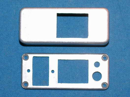
First, we prepared the utility box by cutting the holes for the three Cinch connectors, the RCA phono jack and the grommet for the power cable. The holes for the Cinch connectors were cut to be just big enough to accommodate the front of the connectors. The hole for the twelve pin plug was cut in the bottom of the utility box and slightly offset from center to clear both the R7’s voltage select slide switch on the left and the speaker jack on the right (see figures 4 and 7). The hole for the twelve-pin socket was cut in the lid exactly opposite the hole in the box’s bottom.
The Cinch sockets and plug are designed for chassis mounting (that is, they have what Cinch calls angle brackets) and may be hard to find. However, the twelve-pin socket and plug do not necessarily need the angle brackets, as explained later on. The eight-pin socket will need the angle bracket, though.
The angle brackets (mounting tabs) of the Cinch Jones 12 pin plug and socket were too big to allow mounting in the box and needed to be shortened at about the middle of the mounting holes so that they just fit the inside of the box (since the plug and socket would “float” in the box, the bracket mounting holes weren’t needed).
As shown in the schematic, pins 7, 8 and 10 of the socket are unused so were cut off at the solder end in order to prevent these pins from shorting to the corresponding pins of the plug. Then the Cinch Jones 12 pin plug and socket were wired together back to back, by soldering corresponding plug and socket pins 1-6, 9, 11 and 12 together using small pieces of 22 ga single strand hookup wire. As luck would have it, the resulting assembly height was the same depth as the Bud box. This allowed the assembly to “float” in the adapter, held in place by the angle brackets and the cutouts in the box that were just big enough for the front of the connectors.
Lengths of 22 gage multistrand hookup wire were used to connect pins 3, 7 and 10 of the Cinch Jones 12 pin plug to the 8 pin socket. The completed assembly is shown in figure 5.
Using the R7 accessory jack to correctly orient the polarized plug, we laid the assembly into the box lid. After jumpering pins 5 and 7 of the Cinch Jones 8 pin socket connector (as shown in figure 3), we mounted the 8 pin socket connector, the RCA phone jack and the chassis grommet to the lid of the box. Using the schematic (figure 3) as a guide, we finished wiring the three loose wires and the other end of the 10K resistor to the Cinch Jones 8 pin socket connector and RCA jack (figure 6).
Using a 10” piece of twisted pair 22 gage multistrand hookup, we wired the Amphenol connector to pins 1 and 3 of the Cinch Jones 8 pin socket connector, making sure that we observed the correct polarity (Pin 3 of the Cinch Jones to the + lead and pin 1 to the – lead, using the polarity marked on the back of the R7 next to the mating Amphenol socket.)
We completed the adapter by fastening the box lid to the box using the supplied machine screws, and then plugged the adapter into the accessory plug of the R7. We found that a more secure fit to the R7 was achieved by removing the interfering screw that helps secure the R7’s input voltage selector plate.
Cabling the new adapter simply meant plugging the RV75’s two cables into the adapter and plugging the adapter’s Amphenol plug into the R7’s Amphenol 13.8V socket (this is the source that powers the RV75). See figure 7.
In order for the RV75 to control the R7’s frequency it is necessary to push in the R7’s “fixed” button. To revert back to the R7’s internal VFO, turn the RV75 to off and leave the “fixed” button in the out (off) position.
Click on any picture to enlarge it
Fig 1. Original Drake 1544 adapter.
Fig 2. Original Drake schematic.
Fig 3. Modified schematic.
Fig 4. Die cast box after machining.
Fig 5. The connector and plug joined.
Fig 6. The completed assembly.
Fig 7. The installed adapter.