


The Issue:
The HRO's have a front panel "B+" switch and a rear panel "BSW" terminal, used for receiver muting during transmitting, that control the B+ for a good portion of the receiver's circuitry. When the B+ is switched either on or off, a large "thump" emanates from the speaker. The problem is annoying and potentially harmful to the speaker.
Circuit Analysis:
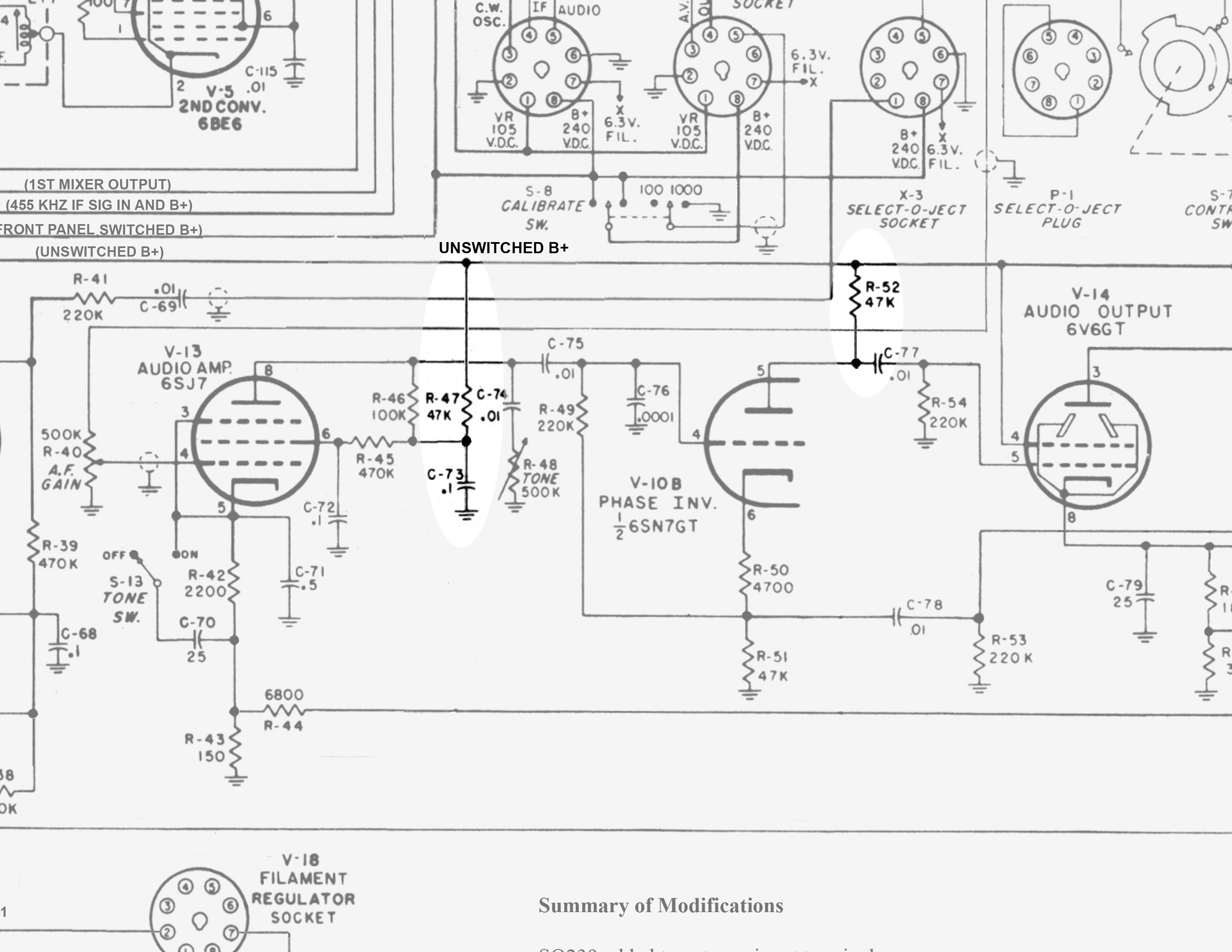
A scope on the switched B+ line confirmed that a large voltage spike (>20V peak) runs line when the B+ is switched either on or off. The spike is fed to the audio amplifier after the AF gain control through the plate supplies of V-13 (the 1st audio amplifier) and V-10B (the audio amp phase inverter).
The HRO also has an unswitched B+ line that supplies the OB2 oscillator voltage regulator, V-16, the CW oscillator V-11 and the screens of the audio output tubes V-14 and V-15. All other B+ voltages in the receiver are fed by the switched B+ line (an exception being the plates supplies to V-14 and V-15 are fed through an unfiltered unswitched B+ to provide a HV load when the B+ is switched off).
A review of later National receiver designs showed that the last National receiver that used B+ switching for muting seems to be the NC-400. In that receiver, only the RF chain's B+ was switched. The entire audio amplifier circuit remained energized during transmit period.
Resolution:
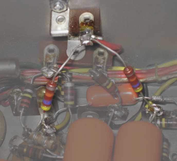
Lift the two 47K plate resistors for V-13, R47 and V-10B, R52 from the switched B+ line and feed the B+ for these two tubes from the unswitched B+ line. The closest point for unswitched B+ is the screen, pin 4, of V-14. A new tie point was created by added a small terminal strip to the side of the chassis between V-13 and V-10 fastened by an unused hole in the chassis. A new wire was run between pin 4 of V-14 and the tie point. The original R47 and R52 were replaced with new 47K resistors routed to the tie point.
Results:
Switching the B+ on and off was now quiet and no other discernable difference in performance was noted.
The HRO's have a front panel "B+" switch and a rear panel "BSW" terminal, used for receiver muting during transmitting, that control the B+ for a good portion of the receiver's circuitry. When the B+ is switched either on or off, a large "thump" emanates from the speaker. The problem is annoying and potentially harmful to the speaker.
Circuit Analysis:
A scope on the switched B+ line confirmed that a large voltage spike (>20V peak) runs line when the B+ is switched either on or off. The spike is fed to the audio amplifier after the AF gain control through the plate supplies of V-13 (the 1st audio amplifier) and V-10B (the audio amp phase inverter).
The HRO also has an unswitched B+ line that supplies the OB2 oscillator voltage regulator, V-16, the CW oscillator V-11 and the screens of the audio output tubes V-14 and V-15. All other B+ voltages in the receiver are fed by the switched B+ line (an exception being the plates supplies to V-14 and V-15 are fed through an unfiltered unswitched B+ to provide a HV load when the B+ is switched off).
A review of later National receiver designs showed that the last National receiver that used B+ switching for muting seems to be the NC-400. In that receiver, only the RF chain's B+ was switched. The entire audio amplifier circuit remained energized during transmit period.
Resolution:
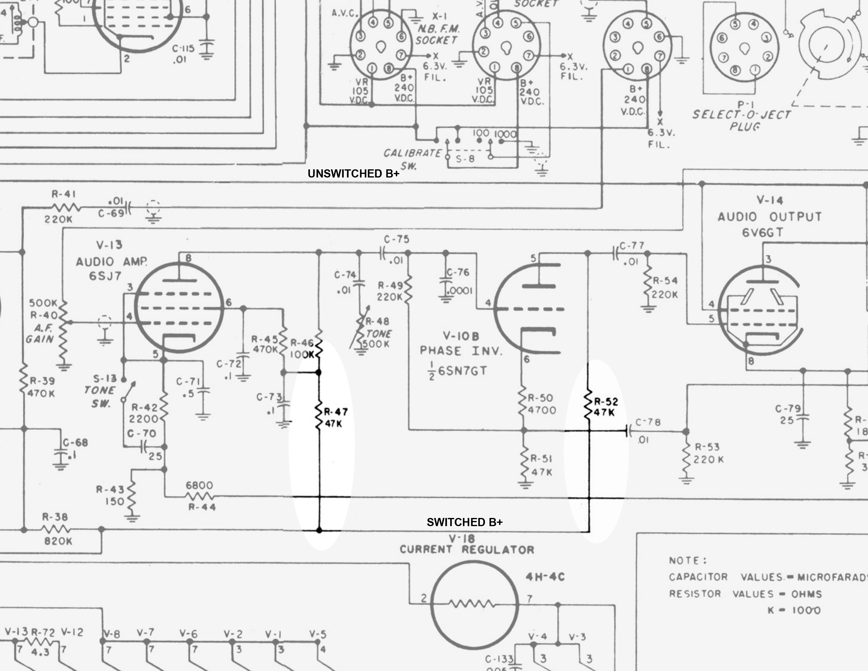
Lift the two 47K plate resistors for V-13, R47 and V-10B, R52 from the switched B+ line and feed the B+ for these two tubes from the unswitched B+ line. The closest point for unswitched B+ is the screen, pin 4, of V-14. A new tie point was created by added a small terminal strip to the side of the chassis between V-13 and V-10 fastened by an unused hole in the chassis. A new wire was run between pin 4 of V-14 and the tie point. The original R47 and R52 were replaced with new 47K resistors routed to the tie point.
Results:
Switching the B+ on and off was now quiet and no other discernable difference in performance was noted.
Click on any picture to enlarge it
Partial original HRO-60 schematic
Revised schematic
Added tie point and relocated resistors